Train Track Building Robot
ProjectIntro
For my final project in the Northwestern MSR program, I focused on creating an autonomous system. This system enables a robot to independently identify, design, and assemble objects within its environment, responding to specific requirements without requiring human intervention.
Full run video will not available until final paper is published. Some short timelapse videos below will show some components in the system and provide some simple concepts of the system.
Project
For this project, the goal was to test the concept of autonomous construction. The robot was tasked with building a complete toy train track circuit, utilizing track pieces randomly placed by humans in the working space. Through collaboration with Professor Michael Rubenstein, Matthew Elwin, and Ph.D. Shane Deng, we successfully developed the basic structure of the system. The robot executed the task precisely as expected, demonstrating the practical application of autonomous construction in a controlled environment.
Robot is scanning workspace to detect existing tracks
After the detection, a piece of track is automatically generated to connect existing tracks and printed by 3D printer
New part is ejected from the 3D printer
Robot is placing the new track to construct the track loop
Robot placed several tracks successfully and is waiting for the new track to be printed
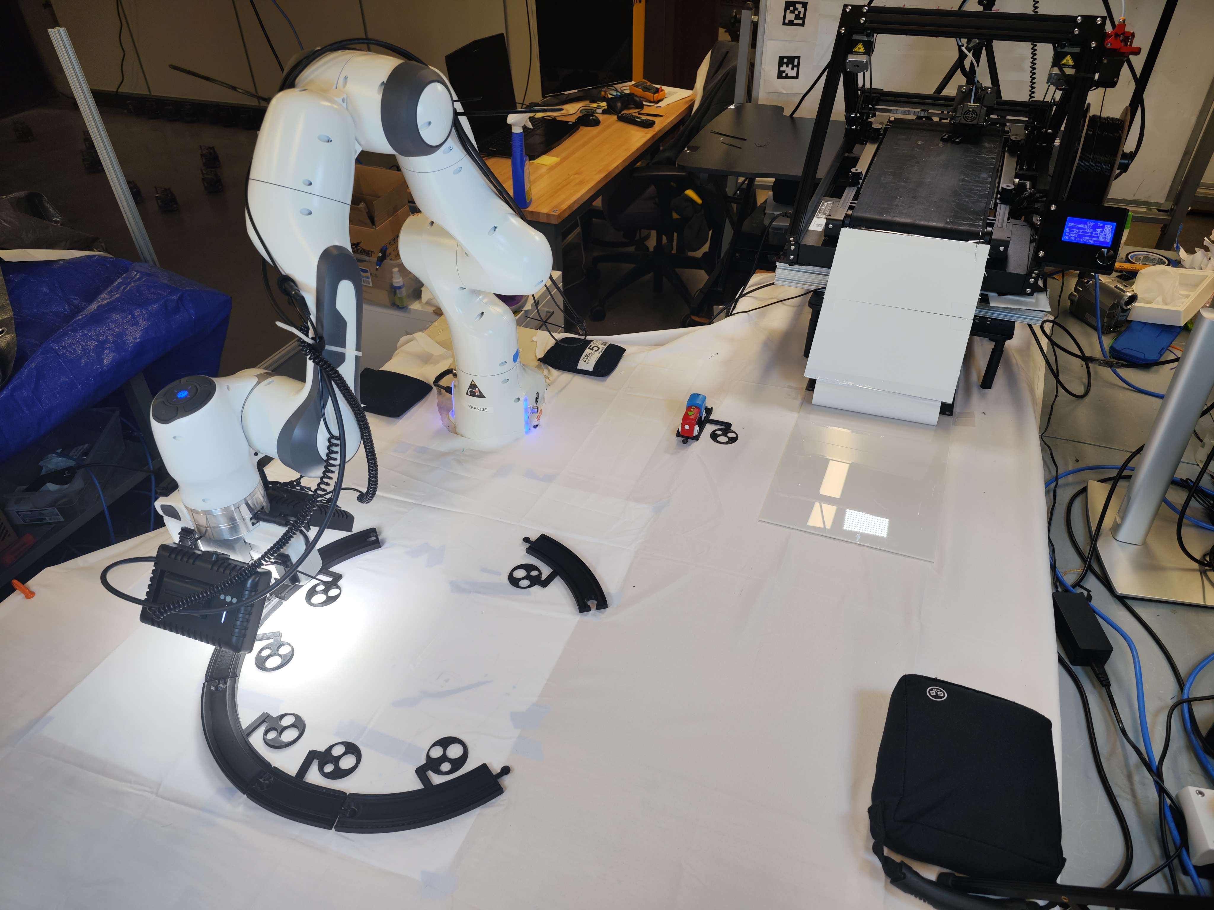
Setup
Hardware
- Franka Emika Panda Cobot
- Intel realsense D435i
- Creatliy CR40 Belt Printer
- Raspberry Pi3 (connected to printer)
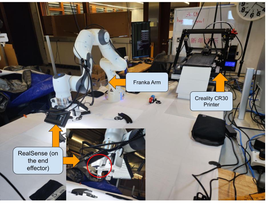
The working space and the hardware setup
Software
- ROS 2
- Opencv
- All packages mentioned in the GitHub Readme
System Design
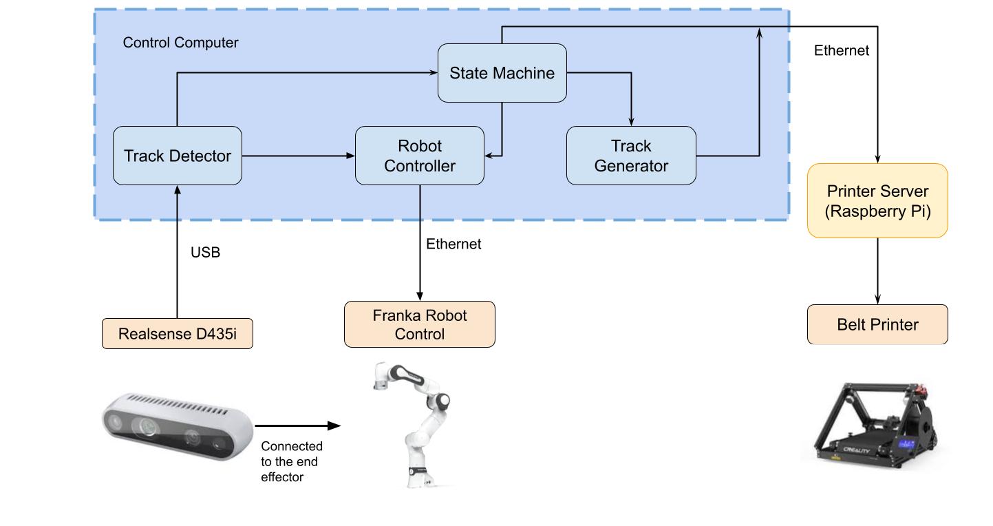
The software system comprises four major components: State Machine, Track Detector, Robot Controller, and Track Generator. The State Machine assumes a central role, orchestrating the entire system and processing tasks sequentially. The block diagram provided illustrates the interdependencies among these key components.
System Design
The State Machine is specifically engineered to command all system components and handle track-related information. The operational logic is elucidated in the following block diagram.
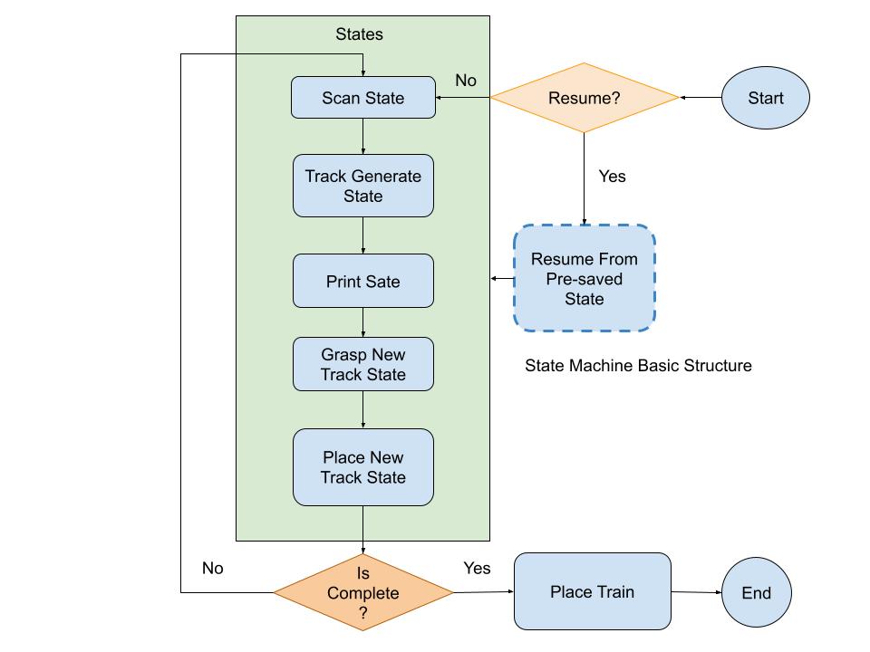
The simplified state machine pipeline
The system waits for people to randomly place tracks in the workspace, starting its work once the placement is finished. It then follows the steps outlined in the State Machine to complete the track. In the following sections, we'll discuss each major part of the system in more detail.
Detection - Camera and Tag
After the placement of tracks in the workspace by people is complete, it becomes improtant to update the robot on the current layout of the tracks. For this purpose, a detection system has been incorporated into the project. A key physical component of this system is the Intel RealSense D435i, affixed to the Franka robot's end effector, providing the necessary visual input for the robot to identify tracks in the workspace.
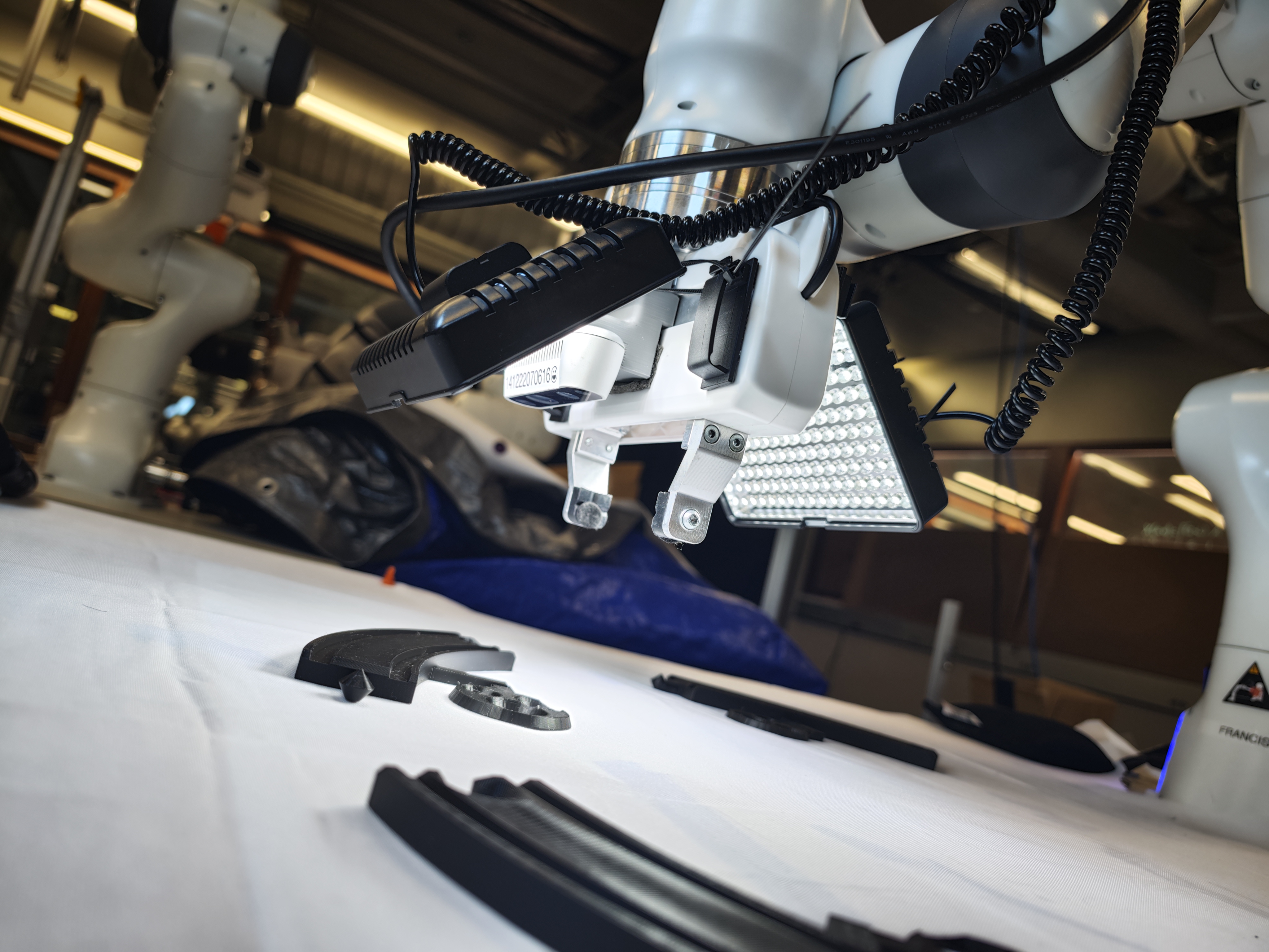
Realsense D435i mounted on the end effector with extra lights
Given the non-uniform shape of the tracks, conventional detection becomes challenging, especially in converting the shapes into positional information. To address this, a fiducial marker system is integrated. In contrast to utilizing existing tag families, a new tag system has been developed. This decision stems from the limitations encountered with other tags, particularly when 3D printed and attached to another part, leading to detection failures due to connectors on tag edges.
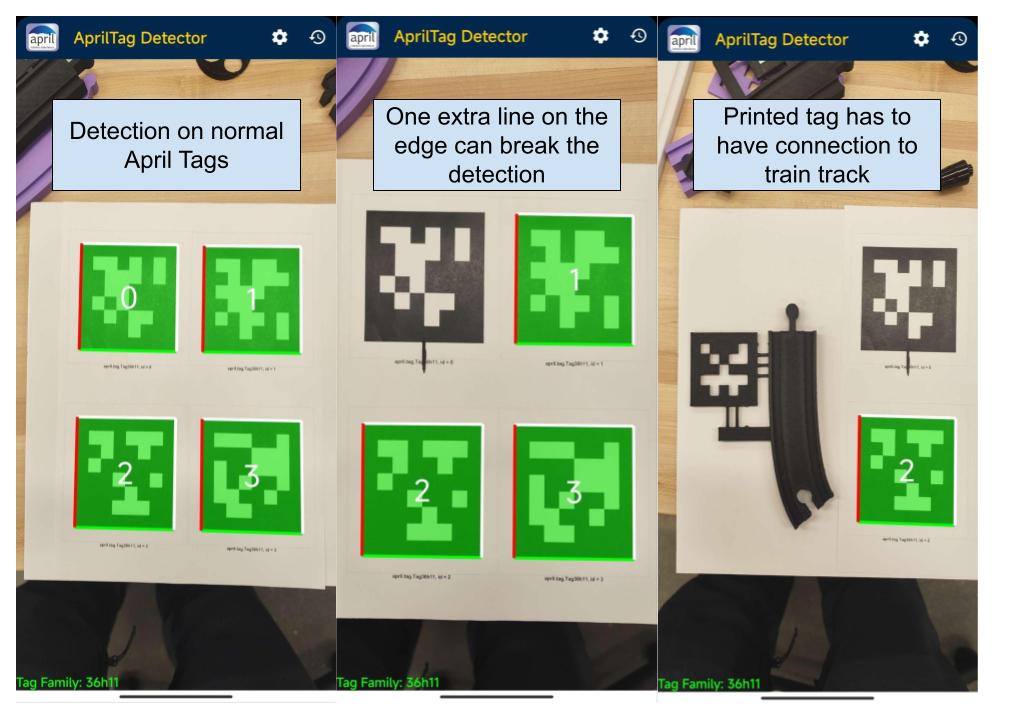
The AprilTag system, known for its maturity in fiducial marking, demands a black border encircled by a continuous white boundary for optimal functionality. Any disruption, even a small connecting line to the border, can compromise detection accuracy.
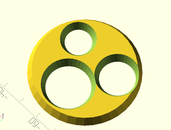
New tag design
The custom-made tag design proves advantageous in detecting the orientation of the track, ensuring detection reliability even if parts of the tag outline are obstructed by connectors. The circular shape chosen for detection enhances robustness, allowing the detector to function effectively even if the circle is incomplete. Once the center of the circles is identified, a PnP (Perspective-n-Point) solver is employed to translate this information from the camera frame into real-world orientation.
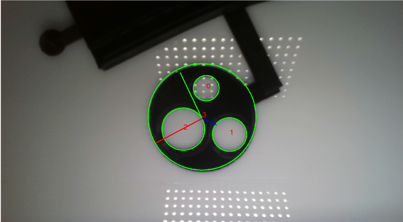
Detecting the Tag position and orientation
The robot system detects all tags within the scanning space, relaying tag position information to the robot controller and state machine. The state machine then updates track information and signals the generator to create the next track.
Right Now a new detector is under testing which could allow us remove the tag from the track
Design - CAD Generator
The track design is based on the Brio toy train track. The system generated intermediate tracks based on the provided start and end track information after scan information updated. After detection, the system reorganizes the tracks into a specific order, forming a closed loop. This track information is then relayed to the generator, updating it each time the detector detect the change in the environment. The Bezier curve generator plays a pivotal role in creating new curves that connect to the given track.
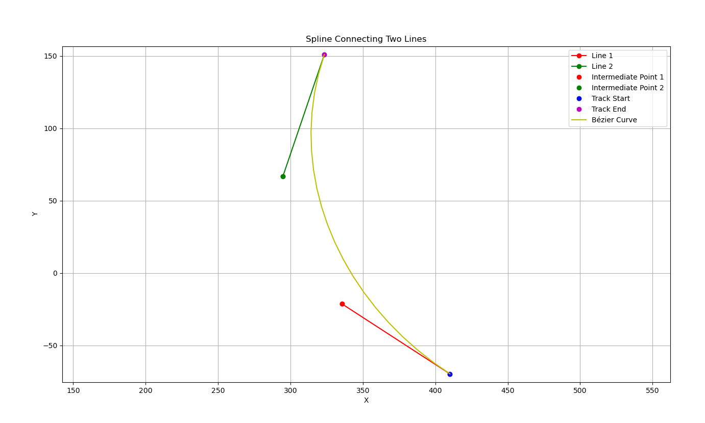
Create Bezier Curve according to the given start and end point information
The system closely monitors the minimum curvature of the generated curve, ensuring that the new track accommodates the original Brio train's passage. Subsequently, the curve is automatically transmitted to a track generator, which generates the track based on the curve's shape. Tags and specially designed connectors are concurrently added to the track. The following image showcases the generated track in the OpenSCAD model.
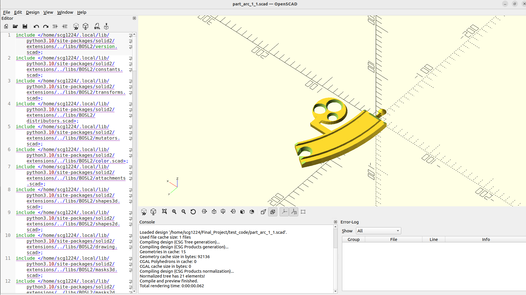
Generate the track cad with tag connected by using Bezier Curve as the reference
OpenSCAD facilitates the conversion of this model into an STL file for processing by the slicer. The slicer, in turn, transforms the design into G-code, suitable for the 3D printer.
(Considerable effort has been invested in this phase to optimize both the tag and track designs, ensuring ease of detection and 3D printing compatibility)
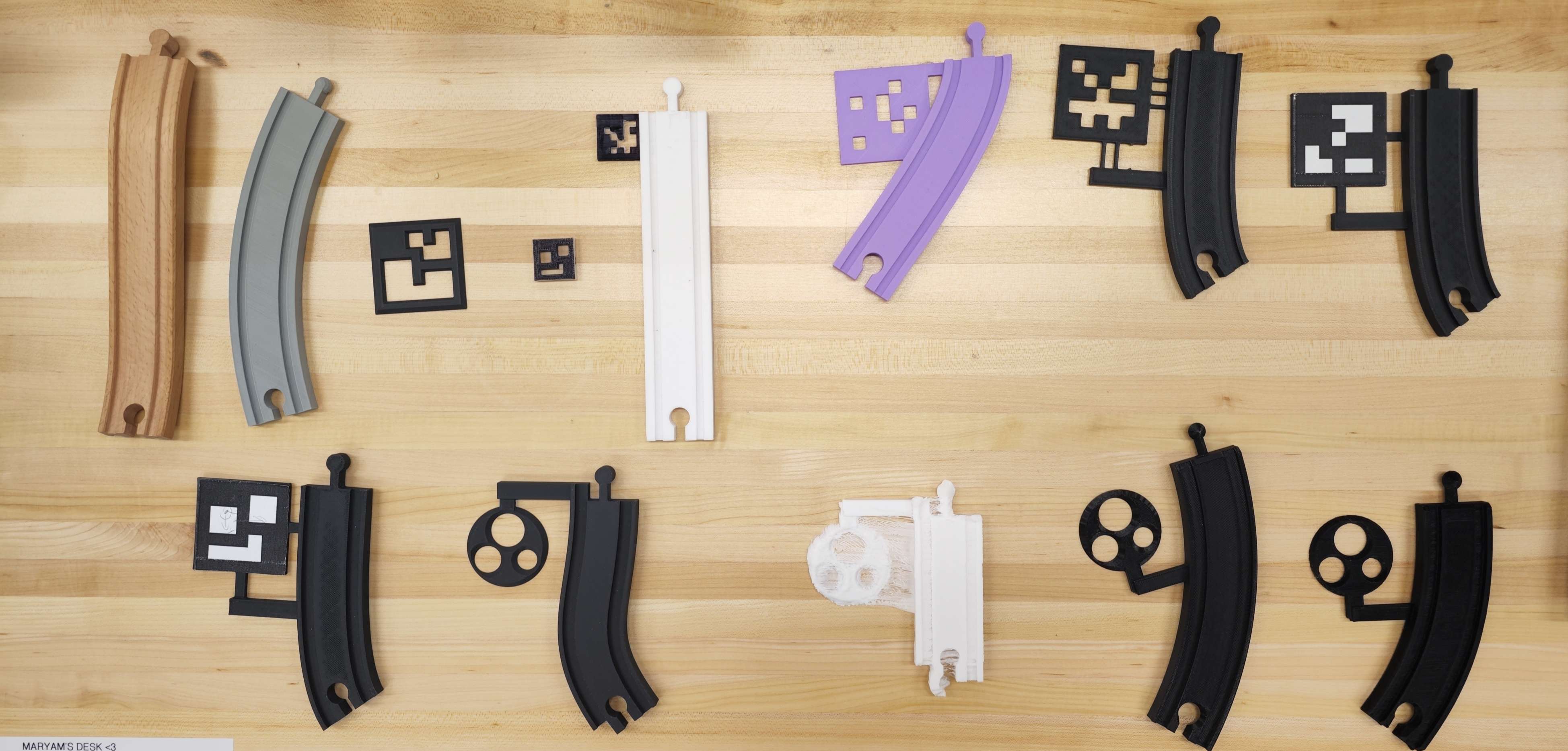
Versions of tags and tracks we developed and tested.
Manufacture - Slicer and Printer:
The slicing process is carried out using Kiri-Moto, offering a command-line interface for seamless integration. Once the STL file is generated, the system converts it to a customized G-code, tailored to meet our specific printing requirements.
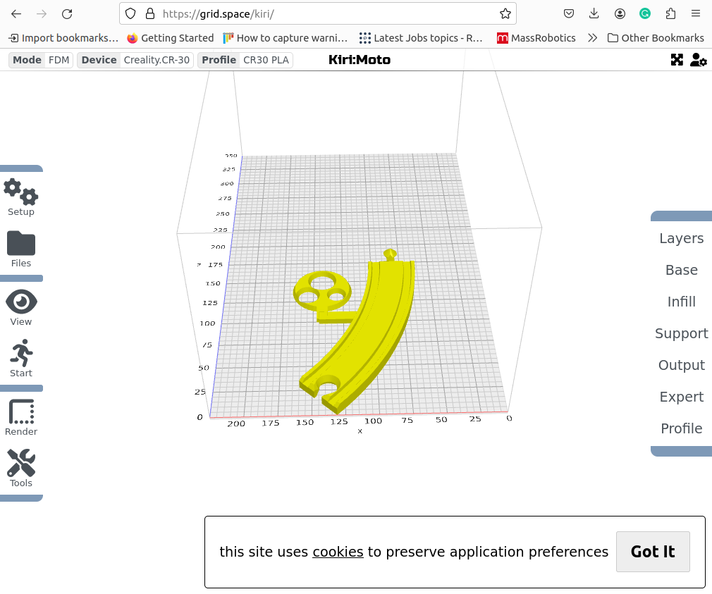
Very useful slicer and works well in command line
The implementation of OctoPrint on a Raspberry Pi, connected to the Creality CR30 printer, streamlines the printing process. Once the G-code is prepared, the control computer transmits the file to the printer, while the Raspberry Pi monitors the print progress and provides real-time status updates.
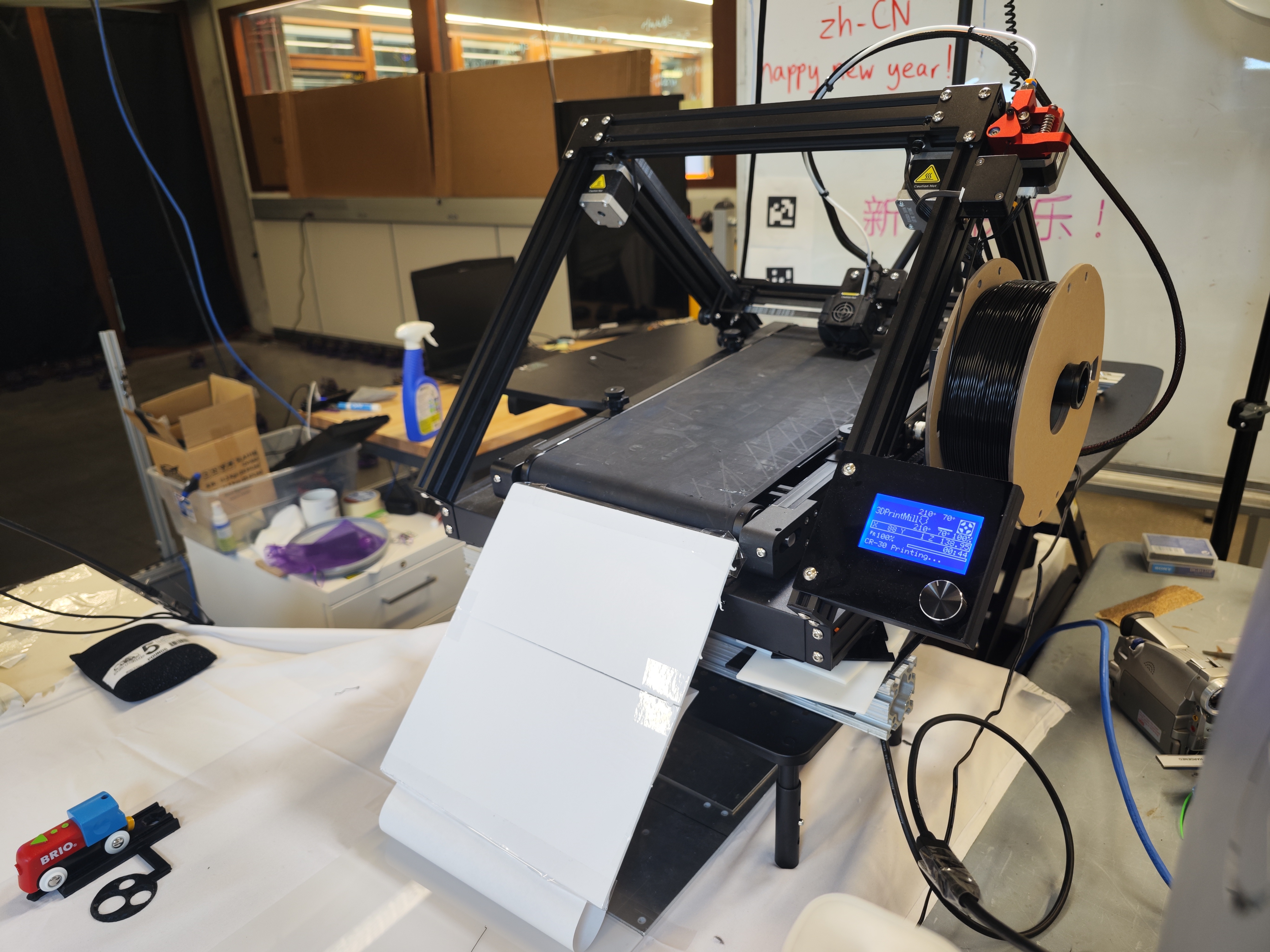
Belt printer is printing new track for the robot system
Given the unique design of the printer as a belt printer, parts are effortlessly ejected from the print bed by simply rolling the belt forward. The newly printed track piece neatly falls into a designated area within the workspace, ready for the robot to collect upon completion of the printing process.
Belt printer is ejecting finished train track (time x9)
Manipulation – Robot
The Franka Emika Panda Cobot arm plays a crucial role in this project. With the camera positioned at the end effector, the robot not only handles the movement of track pieces but also serves as an essential component of the detection pipeline. Additionally, the robot is programmed with specialized movements to enhance detection accuracy and address misalignment issues effectively.
Robot is scanning tracks after system started
Robot is placing the new track to construct the track loop
Future Improvements
Detection Accuracy: Presently, the detection accuracy hovers around 1-2mm. Our goal is to elevate this precision, aiming for a level of accuracy comparable to what April tags can achieve.
Design: While SCAD has been instrumental in our design process, unexpected assertion errors have surfaced during file conversion to STL via the command line. Considering this, we are exploring more stable alternatives for design work in the future.
Manufacture: The current printing time is notably lengthy. Future enhancements could involve optimizing printer performance to boost printing speed or upgrading to a more efficient printer.
Manipulation: The Franka robot experiences intermittent malfunctions, likely due to bugs within the system. Addressing this issue requires revising content in the Franka ROS2 repository to ensure the robot's stability and reliability in operation. This is crucial for the success of the overall project.
Github
More information and source code can be found on the project'sGitHub repository.
(Paper in progress, all code will release to public after paper published)