Autonomous Train Control Robot
ProjectDuring the Winter quarter of 2023, I worked on an independent project in which I designed a control system that utilizes solely visual information to direct the movement of two PincherX 100 robot arms. The objective of the project was to utilize two robot arms to control the train controller, thereby driving the Caltrain's commuter train on Train Sim World - Caltrain's Peninsula Corridor route.
Background
Currently, the majority of train control systems still heavily depend on signal equipment along the rail and other external wireless signal inputs. In addition, some less advanced control systems lack the ability to autonomously regulate train speed, requiring human intervention. Furthermore, most control systems lack the capability to perceive their surrounding environment, which has caused accidents that could potentially be prevented or reduced. For instance, the train derailment which caused by collision with maintenance vehicle that occurred in Chester, Pennsylvania in 2016 resulted in significant damage. However, if computer vision had been implemented into the train control system and detected obstacles on the rail visually at least 8 seconds before the train engineer applied emergency braking manually, the accident could have been significantly mitigated.
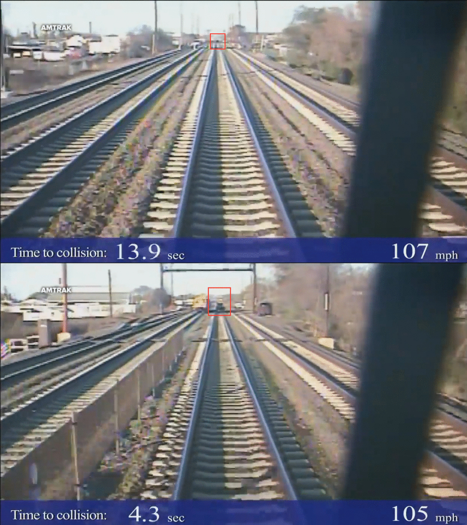
The obstacle on the track was visible at least 13 seconds before the accident occurred, however, the emergency brake was only applied 5 seconds before the impact.
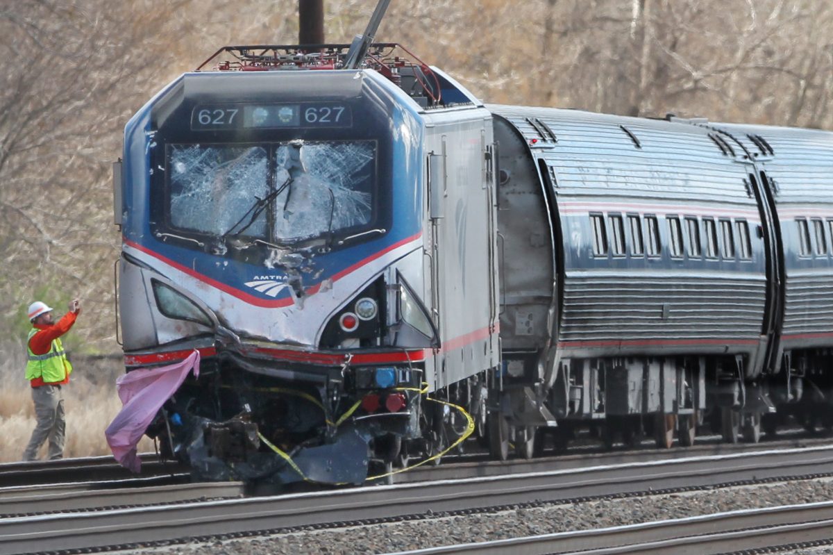
This accident could have been significantly mitigated
Intro
In this project, I successfully designed and implemented a visual-based train control system that can efficiently manage train operations. This system is capable of controlling the train's speed limit and stopping it automatically at the station without the need for human intervention. The system solely relies on visual input, allowing for seamless interaction with the simulator.
The robots are currently controlling the train to approach its next scheduled stop.
This system is a pixel-to-command system, which can work under a limited environment with constrained information.
Moreover, this system is independent of the simulator and interacts with it physically, making it possible to transfer the technology seamlessly to a real train.
Setup
Hardware:
- 2 PincherX 100 robot arm
- One computer runs Train Simulator
- One computer with a 3090 graphic card running the control program (including perception and control)
- One Flint LX graphic card
- A RealSense D435i camera (used as a webcam)
- 3D printed adaptors and laser cutted jig
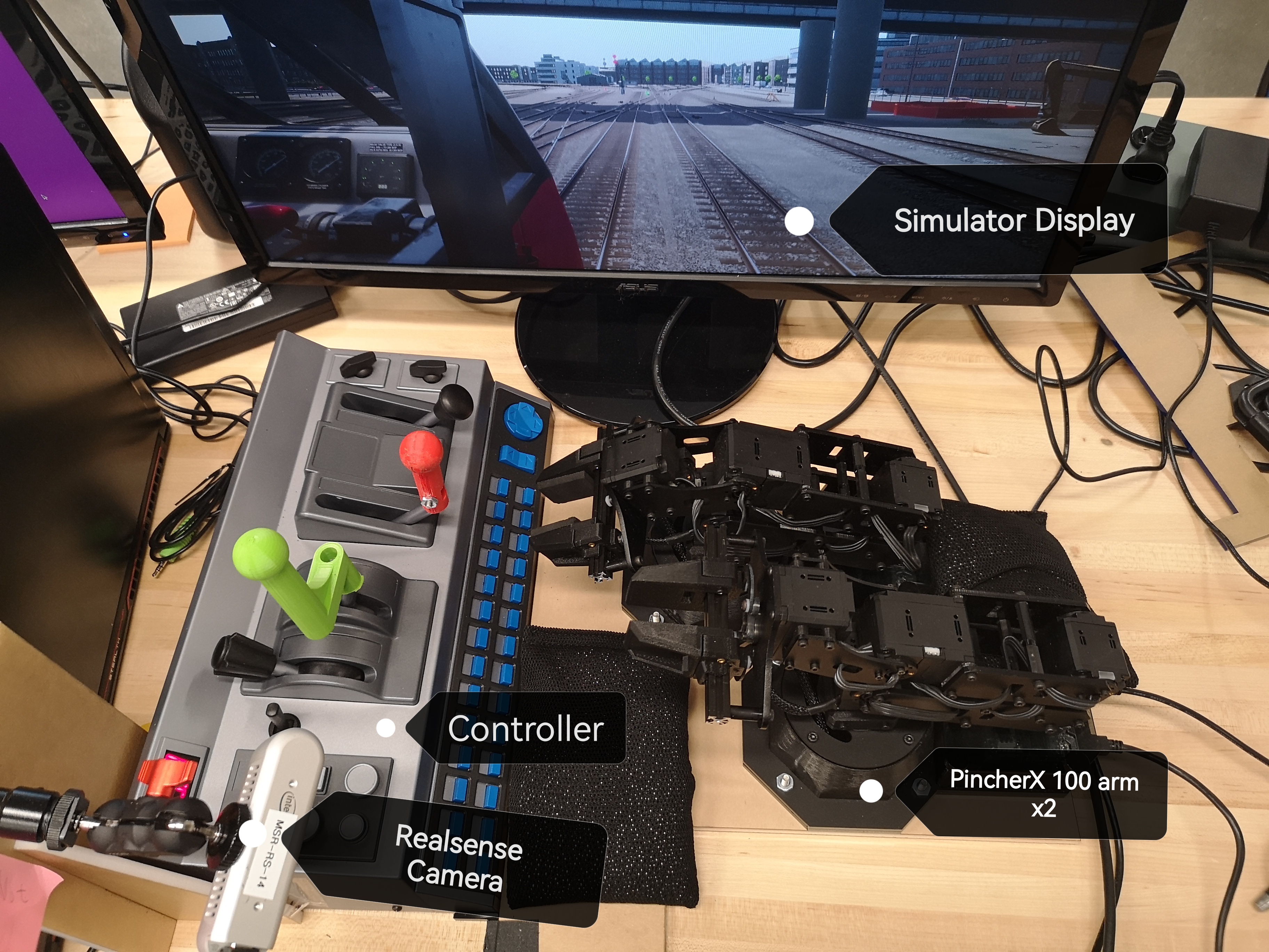
The robot setup for this project. Include other hardwares
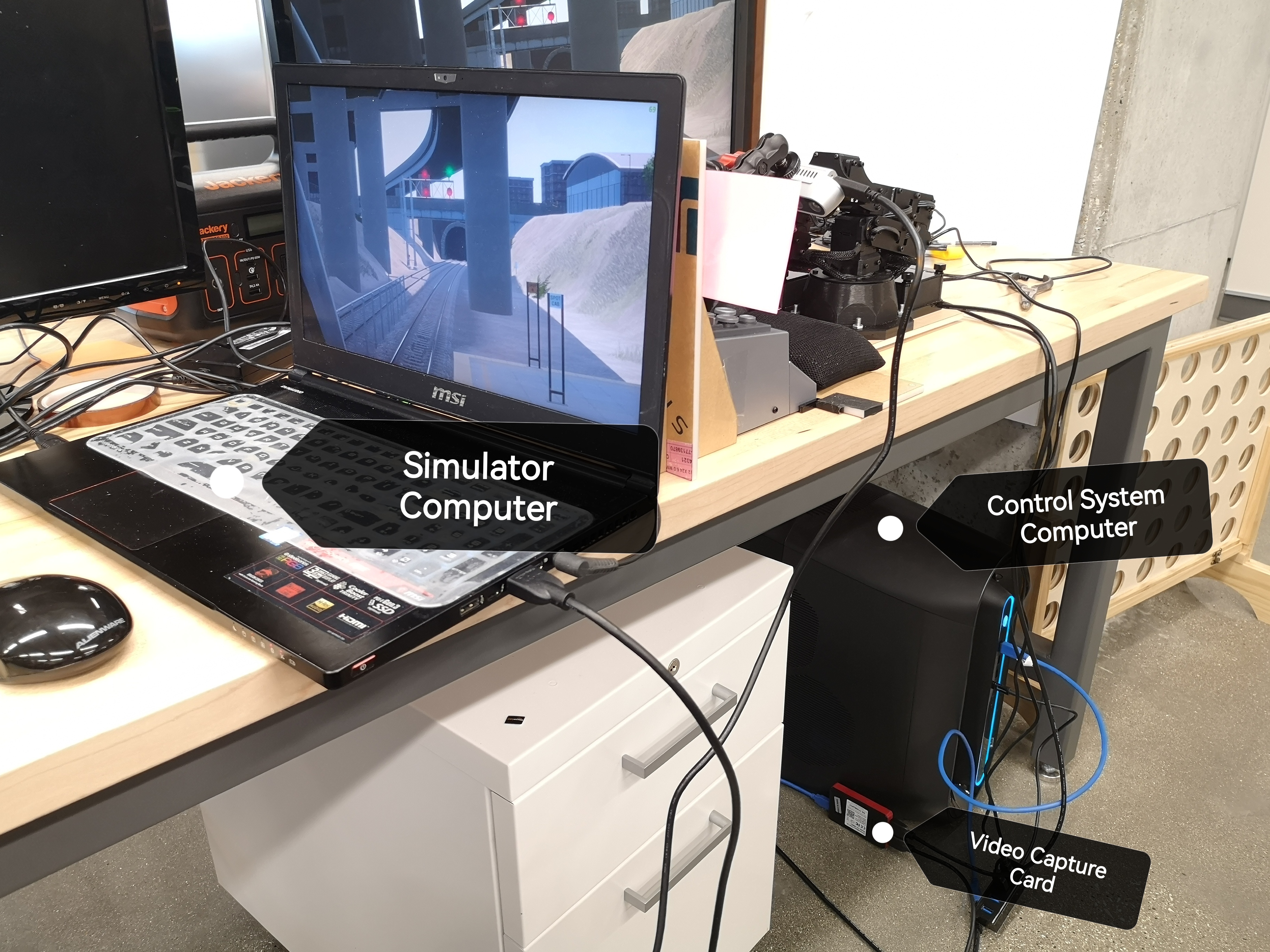
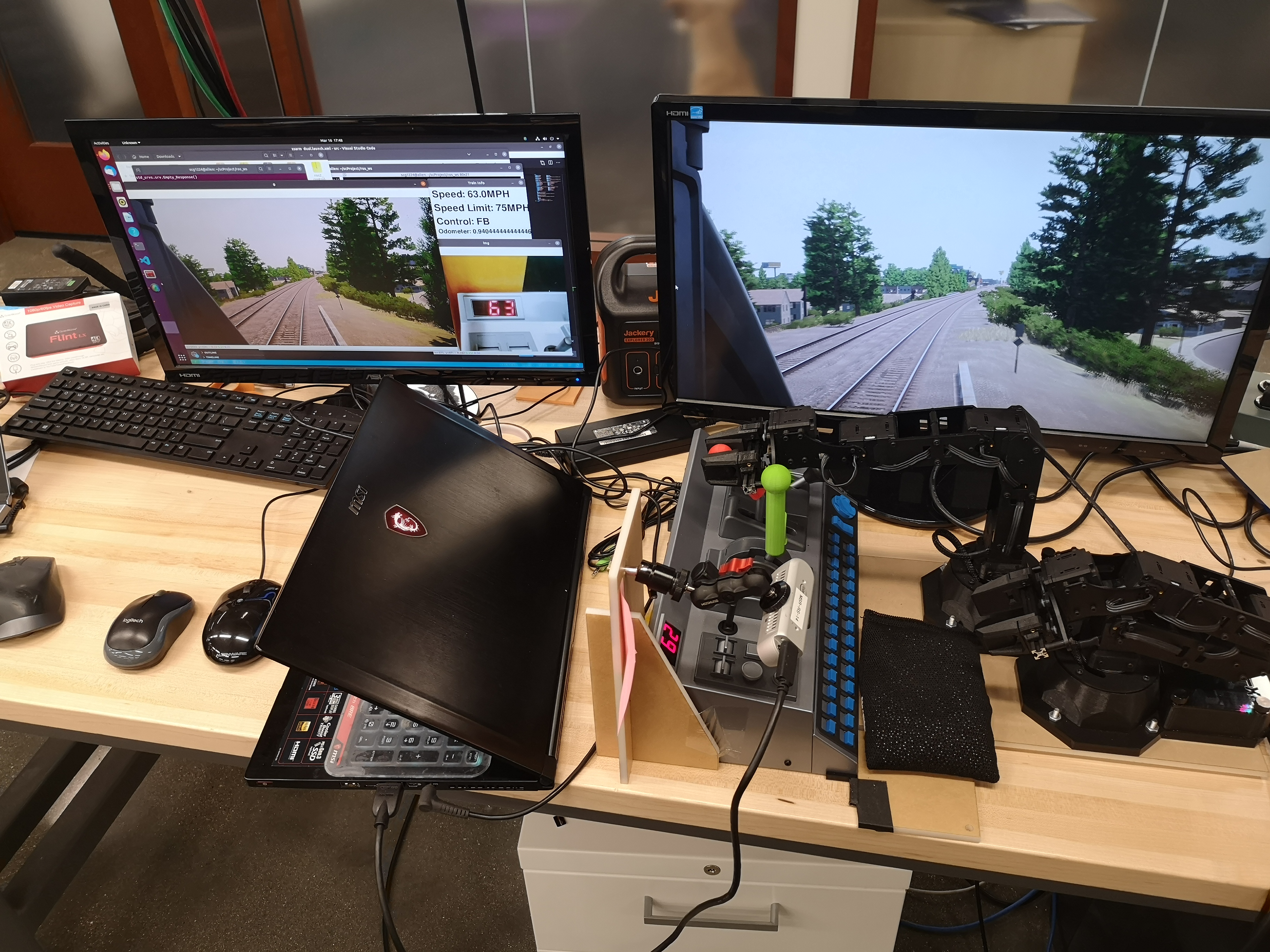
The computers and capture card used for this project
Software:
- Ros2 humble enviroment
- Ubuntu 22.04 (recommended)
- All packages mentioned in the GitHub Readme
The basic pipeline of this system shows below:
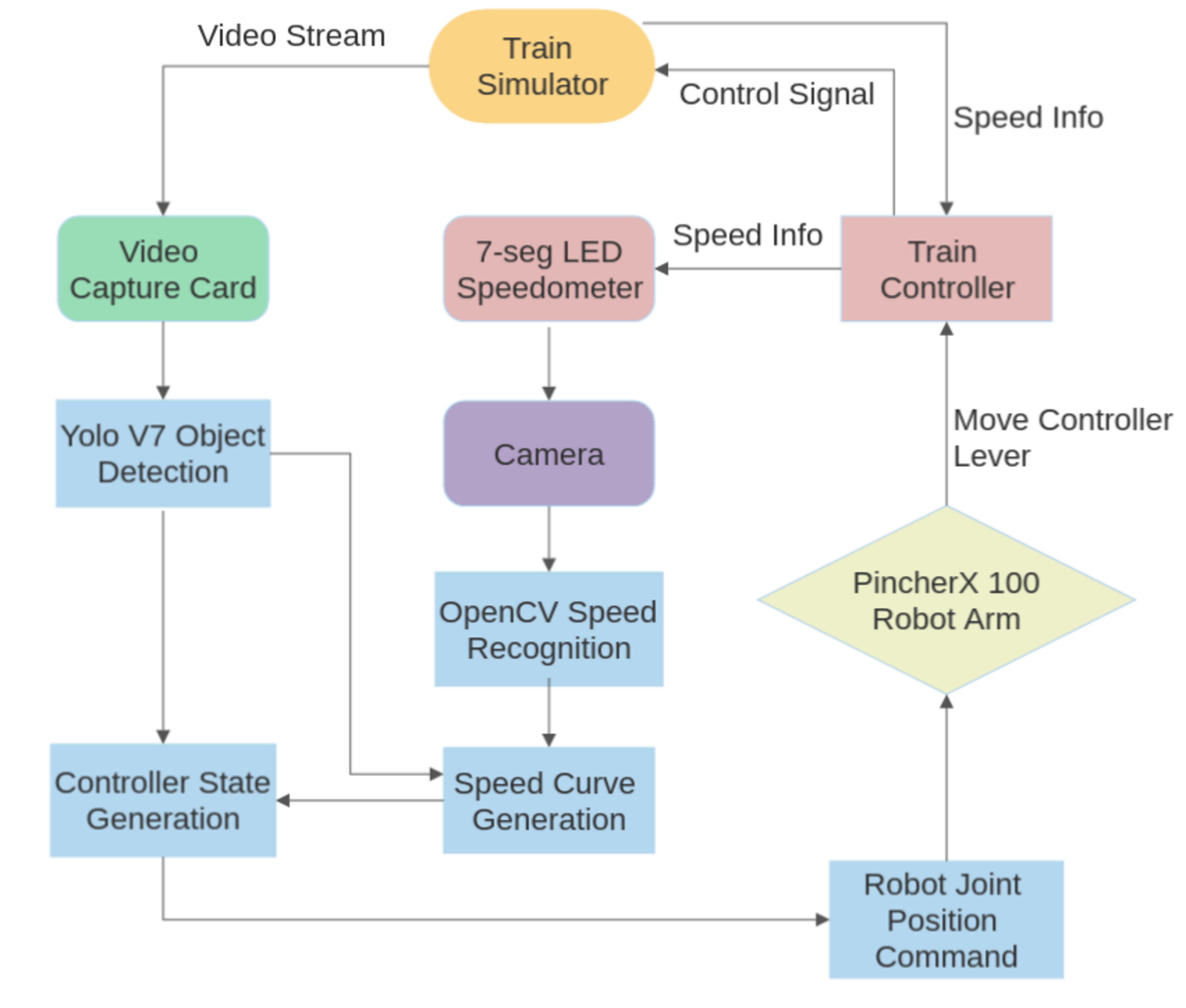
The pipeline of the control system.
All important parts shows up in the flowchart will be discussed below.
Object Detection
Video demo:
The Yolo v7 object detection framework is employed in this project for the purpose of rail marker detection. Through extensive testing, this framework has demonstrated a high degree of accuracy in detecting all the markers along the designated route. In order to achieve this level of performance, a custom training dataset was created specifically for use with YoloV7. Although mileage markers were not categorized in detail within the dataset, all other markers on this route have been classified as independent classes. The detection results obtained through this system will be utilized for generating speed curves and informing controller decision-making processes.
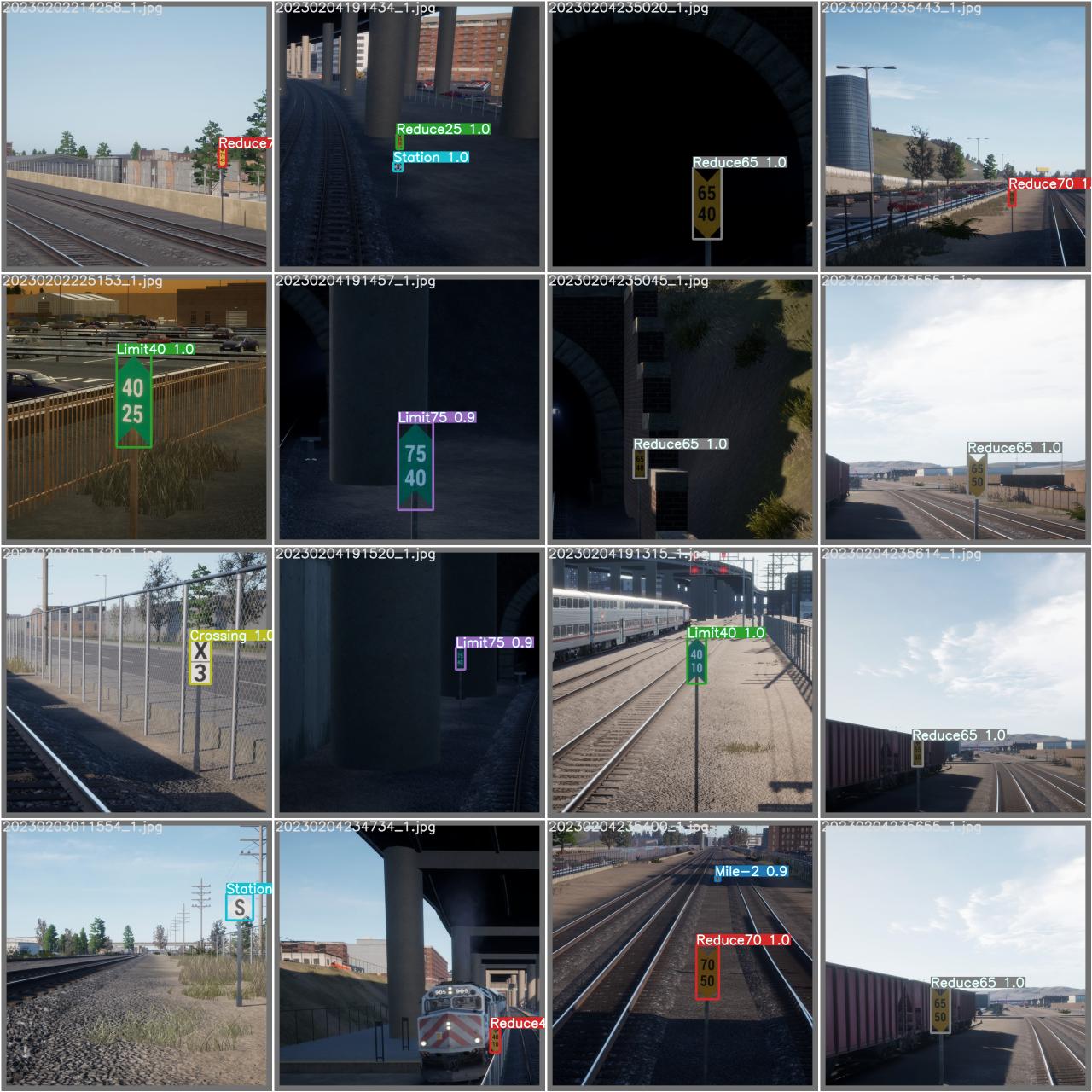
The test result of the final model weight which is used in this project
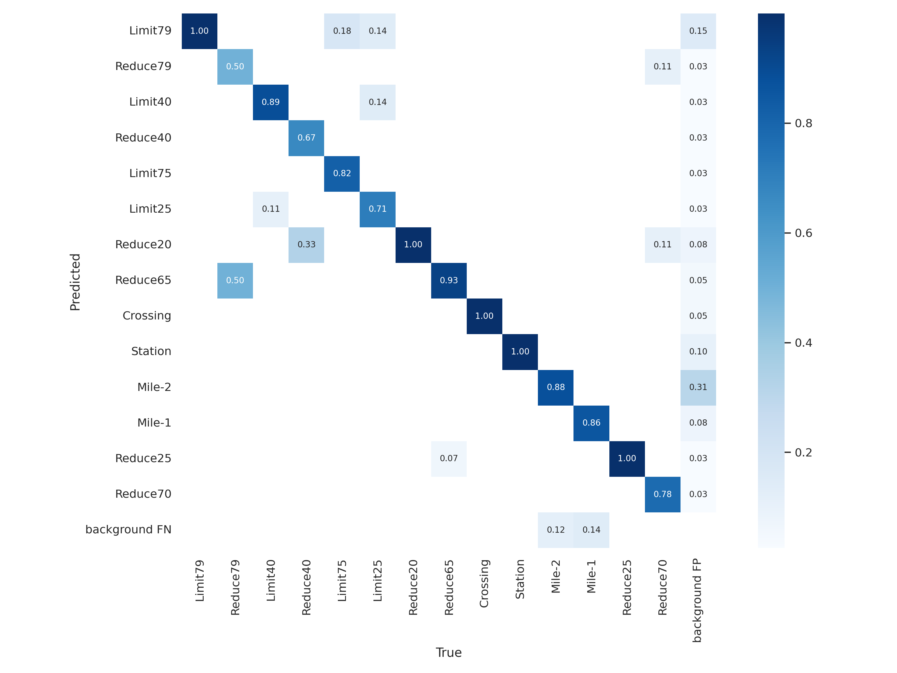
The confusion matrix of this weight
Speed Recognition
Video demo:
The speed information used in this project is sourced directly from the 7-segment LED display on the train's controller. This information is captured through the Realsense camera, which provides an image of the current speed display. The image data is then processed using OpenCV to extract the relevant value, which is subsequently used by the train control system to regulate the train's speed.
Speed Curve
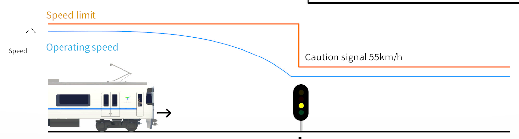
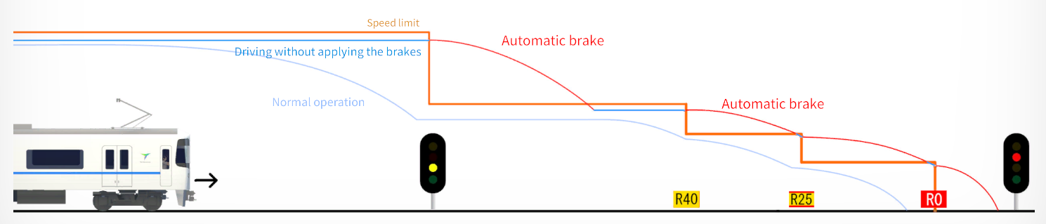
Examples of speed curve implemented in normal train operation
The speed curve is generated based on the current speed limit and station approaching status. This curve serves as a crucial reference point for the train's speed, and the controller is programmed to follow it closely to ensure accurate and autonomous control. By constantly referencing the speed curve, the train control system can regulate the train's speed efficiently, while also ensuring that it adheres to the predetermined speed limits and stops correctly at the designated station.
Controller State Generation
I encountered a challenge due to the high response time of the train to the control input, coupled with the long robot arm moving time in this project. To address this issue, I designed the train controller to generate commands that could eliminate the control overshoot problem, thereby ensuring that the train's speed remained within the predetermined limits. Furthermore, the controller was programmed with different control behaviors to suit various operational environments, enhancing the system's overall flexibility and adaptability.
Robot Control
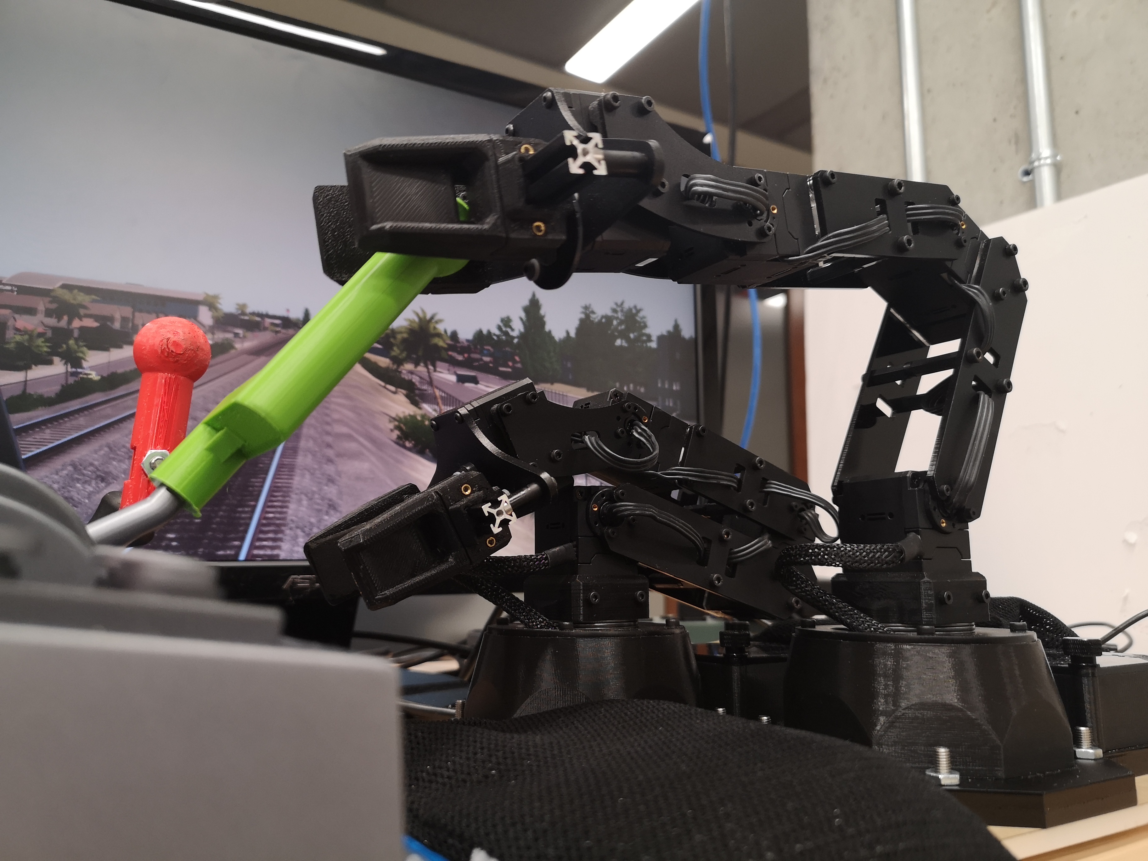
The robots are driving the train
In this project, I utilized two PincherX 100 robotic arms to manipulate the train speed. One arm is dedicated to throttle control, while the other controls the brakes. By using two robotic arms in this manner, I was able to significantly increase the response speed of the system. This approach allows for precise and timely adjustments to be made to the train's speed, enabling it to follow the predetermined speed curve more accurate than the single arm.
Future Work:
-
Utilize the detected information to construct a linear map of the railroad and accurately determine the train’s location while it is in motion.
-
Incorporate visual railroad signal detection and signal rule logic into the train control system for effective implementation.
-
Visual odometry to get better distance measurement.
-
Autonomous train horn and bell.
Github
More information and source code can be found on the project's GitHub repository.